TM-9-2320-272-23-3 - Page 1311 of 1469
REMOVAL
1.
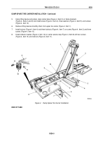
Remove two locknuts (Figure 1, Item 6), screws (Figure 1, Item 3), and washers (Figure 1, Item 4) from carrier
base (Figure 1, Item 1) and frame bracket (Figure 1, Item 5). Discard locknuts.
2.
Remove two locknuts (Figure 1, Item 8), screws (Figure 1, Item 2), and carrier base (Figure 1, Item 1) from
frame brackets (Figure 1, Items 5 and 7). Discard locknuts.
3
4
5
M5086DAA
1
2
6
7
8
Figure 1.
Spare Tire Carrier Removal.
END OF TASK
INSTALLATION
1.
Position carrier base (Figure 2, Item 1) on frame brackets (Figure 2, Items 5 and 7).
2.
Install carrier base (Figure 2, Item 1) on frame brackets (Figure 2, Items 5 and 7) with two screws
(Figure 2, Item 2), locknuts (Figure 2, Item 8), washers (Figure 2, Item 4), screws (Figure 2, Item 3), and locknuts
(Figure 2, Item 6).
TM 9-2320-272-23-3
0525
0525-2
Back to Top


