TM-9-2320-272-23-3 - Page 151 of 1469
REMOVAL
NOTE
•
For inspection and repair of front wiring harness, refer to (WP
0352).
•
Tag wires and connectors for installation.
1.
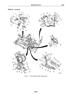
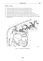
Remove nut (Figure 1, Item 4), lockwasher (Figure 1, Item 3), and wire (Figure 1, Item 6) from solenoid
(Figure
1,
Item
1). Discard lockwasher.
2.
Remove nut (Figure 1, Item 8), lockwasher (Figure 1, Item 7), battery cable (Figure 1, Item 10), and wire
(Figure
1,
Item
9) from solenoid (Figure 1, Item 1). Discard lockwasher.
3.
Remove nut (Figure 1, Item 5), lockwasher (Figure 1, Item 2), and wire (Figure 1, Item 12) from starter
(Figure
1,
Item
16). Discard lockwasher.
4.
Remove nut (Figure 1, Item 13), lockwasher (Figure 1, Item 11), and wires (Figure 1, Items 14 and 15) from
starter (Figure 1, Item 16). Discard lockwasher.
5.
Remove two screw assembled lockwashers (Figure 1, Item 32) and terminal cover (Figure 1, Item 31) from
alternator (Figure 1, Item 26). Discard screw assembled lockwashers.
NOTE
Sealing compound must be removed from wiring before removing wires.
6.
Disconnect wire (Figure 1, Item 34) from lead (Figure 1, Item 35).
7.
Remove screw (Figure 1, Item 36), lockwasher (Figure 1, Item 37), and wire (Figure 1, Item 38) from alternator
(Figure 1, Item 26). Discard lockwasher.
8.
Remove nut (Figure 1, Item 28), lockwasher (Figure 1, Item 27), and wire (Figure 1, Item 39) from alternator
(Figure 1, Item 26). Discard lockwasher.
9.
Remove nut (Figure 1, Item 30), lockwasher (Figure 1, Item 29), and wire (Figure 1, Item 33) from alternator
(Figure 1, Item 26). Discard lockwasher.
10.
Remove screw (Figure 1, Item 51), clamp (Figure 1, Item 52), and front wiring harness (Figure 1, Item 50) from
engine block (Figure 1, Item 40).
11.
Remove screw (Figure 1, Item 46), washer (Figure 1, Item 45), ground strap (Figure 1, Item 44), and ground
wires (Figure 1, Items 41, 42, and 43) from engine block (Figure 1, Item 40).
12.
Remove screw (Figure 1, Item 48), washer (Figure 1, Item 47), clamp (Figure 1, Item 49), and wiring harnesses
(Figure 1, Items 50 and 53) from engine block (Figure 1, Item 40).
13.
Disconnect wire (Figure 1, Item 25) from coolant temperature sending unit (Figure 1, Item 24).
14.
Remove locknut (Figure 1, Item 20), washer (Figure 1, Item 21), screw (Figure 1, Item 23), washer
(Figure
1,
Item
21), clamp (Figure 1, Item 22), and front wiring harness (Figure 1, Item 18) from radiator
(Figure
1,
Item
19). Discard locknut.
15.
Disconnect wiring harness (Figure 1, Item 18) from front lights cable receptacle (Figure 1, Item 17).
TM 9-2320-272-23-3
0358
0358-2
Back to Top


