TM-9-2320-272-23-3 - Page 277 of 1469
INSTALLATION
NOTE
Vehicle must be started in N (neutral) to check selector lever assembly. Vehicle will start if
installation is correct. Remove and reinstall selector lever assembly if vehicle fails to start in
N (neutral).
1.
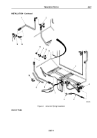
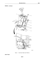
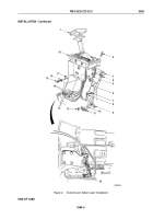
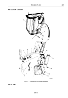
Place selector lever (Figure 2, Item 1) in neutral position.
2.
Place manual control linkage arm (Figure 2, Item 19) in neutral position. Linkage arm will be one detent down
from full up position.
3.
Install shim (Figure 2, Item 9), shift cable (Figure 2, Item 10), and cable clamp (Figure 2, Item 11) on hanger
plate (Figure 2, Item 6) with two washers (Figure 2, Item 8), screws (Figure 2, Item 7), and nuts
(Figure
2,
Item
12). Ensure cable clamp seats in groove of shift cable housing.
4.
Loosen jamnut (Figure 2, Item 4) and align cable trunnion (Figure 2, Item 3) with first hole above elongated
slot in selector lever plate (Figure 2, Item 5). Cable trunnion is turned clockwise to shorten and counterclockwise
to lengthen. Tighten jamnut and install in plate with spring clip (Figure 2, Item 2).
5.
Connect three electrical leads (Figure 2, Item 14) to harness leads (Figure 2, Item 13).
6.
Install selector lever assembly (Figure 2, Item 18) in control lever console (Figure 2, Item 17) with four
lockwashers (Figure 2, Item 16) and screws (Figure 2, Item 15).
TM 9-2320-272-23-3
0369
0369-4
Back to Top


