TM-9-2320-272-23-3 - Page 281 of 1469
REMOVAL
NOTE
Vehicles equipped with winch will have winch control tower attached to shift tower. Two
screws and washers in Step (1) will be removed from winch control tower.
1.
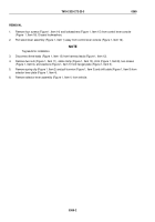
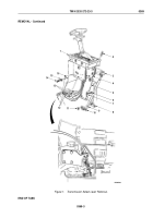
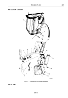
Remove four screws (Figure 1, Item 4), washers (Figure 1, Item 3), and shift tower (Figure 1, Item 2) from
access cover (Figure 1, Item 1).
NOTE
Perform Steps (2) through (7) for M939A2 series vehicles.
2.
Remove two screws (Figure 1, Item 5) and washers (Figure 1, Item 6) from bracket (Figure 1, Item 7) and front
mount bracket (Figure 1, Item 12).
3.
Remove screw (Figure 1, Item 15) and rear mount bracket (Figure 1, Item 14) from shift tower base
(Figure
1,
Item
13).
4.
Remove screw (Figure 1, Item 10) and front mount bracket (Figure 1, Item 12) from shift tower base
(Figure
1,
Item
13).
5.
Remove grommet (Figure 1, Item 11) from front mount bracket (Figure 1, Item 12).
6.
Remove four screws (Figure 1, Item 9), lockwashers (Figure 1, Item 8), shift tower base (Figure 1, Item 13),
and gasket (Figure 1, Item 16) from mounting bracket (Figure 1, Item 17). Discard lockwashers and gasket.
7.
Remove seven screws (Figure 1, Item 18), lockwashers (Figure 1, Item 19), and mounting bracket
(Figure
1,
Item
17) from floor (Figure 1, Item 20). Discard lockwashers.
TM 9-2320-272-23-3
0370
0370-2
Back to Top

