TM-9-2320-272-23-3 - Page 539 of 1469
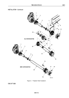
INSTALLATION
NOTE
Perform Steps (1) through (5) for M927A2, M928A2, M934A2, and M935A2 models only.
1.
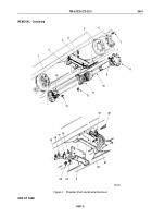
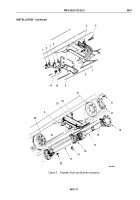
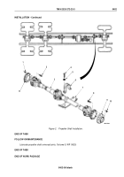
Install bracket (Figure 5, Item 9) on crossmember (Figure 5, Item 8) with three screws (Figure 5, Item 7),
washers (Figure 5, Item 10), and locknuts (Figure 5, Item 11).
2.
Install clamps (Figure 5, Items 3 and 5) on bracket (Figure 5, Item 9) and crossmember (Figure 5, Item 8) with
screw (Figure 5, Item 6), spacer (Figure 5, Item 4), washer (Figure 5, Item 2), and locknut (Figure 5, Item 1).
NOTE
Assistant will help with Steps (5) through (7).
3.
Holding forward-rear axle propeller shaft (Figure 5, Item 17) on brake drum studs (Figure 5, Item 22) and
forward-rear axle flange (Figure 5, Item 14), install center bearing (Figure 5, Item 18) on bracket
(Figure
5,
Item
9) with two washers (Figure 5, Item 23), screws (Figure 5, Item 24), and locknuts
(Figure
5,
Item
19).
4.
Install flange (Figure 5, Item 21) on eight transfer case brake drum studs (Figure 5, Item 22) with locknuts
(Figure
5, Item 20). Tighten locknuts 32 to 40 lb-ft (43 to 54 N·m) in alternate sequence.
5.
Install vibration dampener (Figure 5, Item 12) and flange (Figure 5, Item 15) on forward-rear flange
(Figure
5,
Item
14) with eight screws (Figure 5, Item 13) and locknuts (Figure 5, Item 16). Tighten locknuts
30 to 40 lb-ft (43 to 54 N·m).
TM 9-2320-272-23-3
0401
0401-10
Back to Top


