TM-9-2320-272-23-3 - Page 679 of 1469
INSTALLATION
NOTE
Assistant will assist with Step (1).
1.
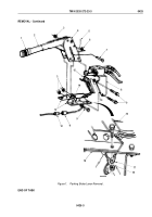
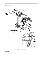
Install wire (Figure 2, Item 17) on cab floor (Figure 2, Item 19) with screw (Figure 2, Item 16) and locknut
(Figure
2,
Item
18).
2.
Connect wire (Figure 2, Item 11) to wire (Figure 2, Item 12).
3.
Install parking brake housing (Figure 2, Item 4) and spring parking brake valve and bracket (Figure 2, Item 8)
on parking brake switch (Figure 2, Item 15) on brackets (Figure 2, Item 13) with three screws
(Figure
2,
Item
9), spacer washer (Figure 2, Item 10), and three locknuts (Figure 2, Item 3).
4.
Install clevis pin (Figure 2, Item 7) on cable clevis (Figure 2, Item 14) with washer (Figure 2, Item 6) and cotter
pin (Figure 2, Item 5).
TM 9-2320-272-23-3
0425
0425-4
Back to Top


