TM-9-2320-272-23-3 - Page 684 of 1469
INSTALLATION
NOTE
•
Ensure arrow stamped on shoe web points to anchor plunger.
•
Brake shoe and lining assemblies must be replaced in sets on both sides of axle with
linings coded to the color and manufacturer.
•
Rear brake mechanisms have one adjusting plunger in each plunger housing. Front brake
mechanisms have two adjusting plungers in rear of plunger housing.
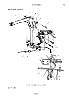
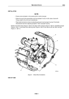
Position two brake shoes (Figure 2, Item 2) into each anchor plunger (Figure 2, Item 5), adjustable plunger
(Figure 2, Item 1), and brake shoe retaining clips (Figure 2, Item 3) and secure with two return springs
(Figure
2,
Item
4).
4
M6175DAA
1
2
3
5
4
3
2
Figure 2.
Brake Shoe Installation.
END OF TASK
TM 9-2320-272-23-3
0426
0426-3
Back to Top

