TM-9-2320-272-23-3 - Page 725 of 1469
INSTALLATION - Continued
10.
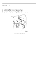
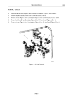
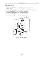
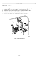
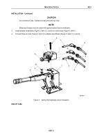
Install adapter (Figure 7, Item 10) and air hose (Figure 7, Item 9) on firewall (Figure 7, Item 1).
11.
Install pipe (Figure 7, Item 11) and tee (Figure 7, Item 6) on firewall (Figure 7, Item 1).
12.
Install adapter (Figure 7, Item 3) and air hose (Figure 7, Item 4) on firewall (Figure 7, Item 1).
13.
Install adapters (Figure 7, Items 5 and 7) on tee (Figure 7, Item 6).
14.
Connect air hoses (Figure 7, Items 2 and 8) to adapters (Figure 7, Items 5 and 7).
M6218DAA
1
2
3
4
5
6
7
8
9
10
11
Figure 7.
Brake Valve Installation.
TM 9-2320-272-23-3
0430
0430-8
Back to Top

