TM-9-2320-272-23-3 - Page 771 of 1469
REMOVAL
WARNING
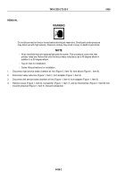
Do not disconnect air lines or hoses before draining air reservoirs. Small parts under pressure
may shoot out with high velocity. Failure to comply may result in injury or death to personnel.
NOTE
•
All air manifold tees are replaced basically the same. This procedure covers the rear
primary relay tee. Notice that only the two primary relay tees use a 45-degree elbow in
addition to a 90-degree elbow.
•
Tag air lines for installation.
•
Scribe fitting directions for installation.
1.
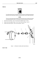
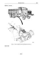
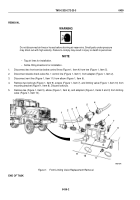
Disconnect right service brake chamber air line (Figure 1, Item 10) from elbow (Figure 1, Item 9).
2.
Disconnect relay valve line (Figure 1, Item 1) from adapter (Figure 1, Item 2).
3.
Disconnect left service brake chamber air line (Figure 1, Item 4) from adapter (Figure 1, Item 3).
4.
Remove screw (Figure 1, Item 6), lockwasher (Figure 1, Item 7), and air manifold tee (Figure 1, Item 8) from
mounting bracket (Figure 1, Item 5). Discard lockwasher.
TM 9-2320-272-23-3
0438
0438-2
Back to Top

