TM-9-2320-272-23-3 - Page 763 of 1469
ADJUSTMENT
NOTE
Whenever governor is adjusted, instrument panel primary air gauge is used.
1.
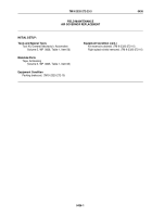
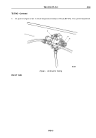
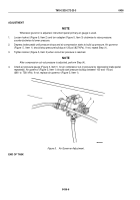
Loosen locknut (Figure 5, Item 2) and turn adapter (Figure 5, Item 3) clockwise to raise pressure;
counterclockwise to lower pressure.
2.
Depress brake pedal until pressure drops and air compression starts to build up pressure. Air governor
(Figure
5,
Item
1) should stop pressure buildup at 120 psi (827 kPa). If not, repeat Step (1).
3.
Tighten locknut (Figure 5, Item 2) when correct air pressure is reached.
NOTE
After compression cut-out pressure is adjusted, perform Step (4).
4.
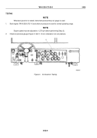
Check air pressure gauge (Figure 3, Item 1) for air compressor cut-in pressure by depressing brake pedal
repeatedly. Air governor (Figure 5, Item 1) should start pressure buildup between 100 and 110 psi
(690
to
758
kPa). If not, replace air governor (Figure 5, Item 1).
1
2
3
M9525DAA
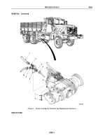
Figure 5.
Air Governor Adjustment.
END OF TASK
TM 9-2320-272-23-3
0436
0436-6
Back to Top

