TM-9-2320-272-23-3 - Page 755 of 1469
BRAKE CHAMBER INSTALLATION
NOTE
Wrap all male pipe threads with antiseize tape before installation.
1.
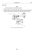
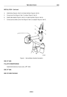
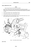
Ensure collet nut (Figure 4, Item 9) is loose, install combination spring and brake service chamber
(Figure
4,
Item 11) in plunger housing (Figure 4, Item 8) until secure, with service brake chamber positioned
for air line connections. Thread collet nut to bottom of service brake chamber and tighten 3/16 in. (4.8 mm) or
1-1/2 teeth.
2.
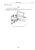
Connect control line (Figure 4, Item 1) to elbow (Figure 4, Item 12).
3.
Connect supply line (Figure 4, Item 13) to elbow (Figure 4, Item 2).
4.
Connect two vent lines (Figure 4, Item 3) to tee (Figure 4, Item 4).
5.
Install U-bolt (Figure 4, Item 10) and bracket (Figure 4, Item 7) on service brake chamber (Figure 4, Item 11)
with two washers (Figure 4, Item 6) and nuts (Figure 4, Item 5).
M6179DAA
1
2
3
4
5
6
9
8
10
11
12
13
7
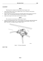
Figure 4.
Service Brake Chamber Installation.
END OF TASK
TM 9-2320-272-23-3
0435
0435-6
Back to Top

