TM-9-2320-272-23-3 - Page 778 of 1469
INSTALLATION
NOTE
Ensure that after applying pipe sealant to all male fittings that the first two starter threads
are
clear.
1.
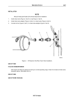
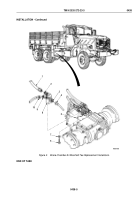
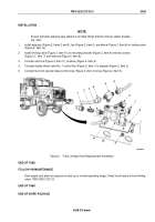
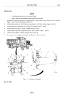
Install adapters (Figure 2, Items 2 and 3), tee (Figure 2, Item 5), and elbow (Figure 2, Item 6) on limiting valve
(Figure 2, Item 10).
2.
Install limiting valve (Figure 2, Item 10) on mounting bracket (Figure 2, Item 8) with two screws
(Figure
2,
Item
7) and locknuts (Figure 2, Item 9).
3.
Connect vent line (Figure 2, Item 11) to elbow (Figure 2, Item 6).
4.
Connect double check valve No. 1 control line (Figure 2, Item 1) to adapter (Figure 2, Item 2).
5.
Connect two front service brake control lines (Figure 2, Item 4) to tee (Figure 2, Item 5).
2
1
3
4
5
4
6
7
8
9
10
11
M9538DAA
Figure 2.
Front Limiting Valve Replacement Installation.
END OF TASK
FOLLOW-ON MAINTENANCE
Start engine and allow air pressure to build up to normal operating range. Check for air leaks at front limiting
valve. (TM 9-2320-272-10)
END OF TASK
END OF WORK PACKAGE
TM 9-2320-272-23-3
0439
0439-3/4 blank
Back to Top

