TM-9-2320-272-23-3 - Page 945 of 1469
INSTALLATION - Continued
8.
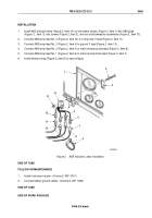
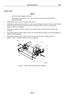
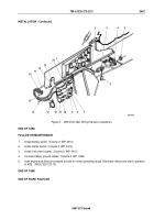
Route harness lead (Figure 6, Item 2), diagnostic connector (Figure 6, Item 3), and ABS main wiring harness
(Figure 6, Item 14) up to front of vehicle and install tiedown straps as necessary.
9.
Route harness lead (Figure 6, Item 2), diagnostic connector (Figure 6, Item 3), and ABS main wiring harness
(Figure 6, Item 14) with leads (10, 11, 12, 18, and 19) through hole (Figure 6, Item 15) in firewall
(Figure
6,
Item
17) and install rubber grommet (Figure 6, Item 6) in hole.
10.
Connect white ground lead (Figure 6, Item 12) from ABS main wiring harness (Figure 6, Item 14) to ground
jumper lead (Figure 6, Item 7).
11.
Connect purple lead (Figure 6, Item 18) from ABS main wiring harness (Figure 6, Item 14) to ABS indicator
lamp lead No. 2 (Figure 6, Item 1).
12.
Connect black lead (Figure 6, Item 19) from ABS main wiring harness (Figure 6, Item 14) to ABS indicator
lamp lead No. 1 (Figure 6, Item 20).
13.
Connect yellow lead (Figure 6, Item 10) from ABS main wiring harness (Figure 6, Item 14) to 3-AMP fuse and
Y-connector lead (Figure 6, Item 8).
14.
Connect red lead (Figure 6, Item 11) from ABS main wiring harness (Figure 6, Item 14) to 15-AMP fuse and
jumper lead (Figure 6, Item 9).
15.
Route harness lead (Figure 6, Item 2) and diagnostic connector (Figure 6, Item 3) over to right side of vehicle
and install diagnostic connector in diagnostic connector bracket (Figure 6, Item 4) with nut (Figure 6, Item 5).
16.
Install cap (Figure 6, Item 6) on diagnostic connector (Figure 6, Item 3).
17.
Secure ABS main wiring harness (Figure 6, Item 14) and harness lead (Figure 6, Item 2) with tiedown straps
(Figure 6, Item 13) as necessary.
TM 9-2320-272-23-3
0467
0467-8
Back to Top

