TM-9-2320-272-23-3 - Page 944 of 1469
INSTALLATION - Continued
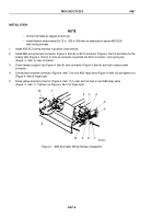
6.
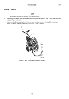
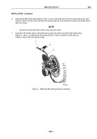
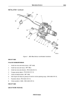
Route yellow 2B harness lead (Figure 5, Item 1) over to right side and connect to right wheel sensor lead
(Figure 5, Item 3) (shown) and route blue 2A harness lead over to left side and connect to left wheel sensor
lead (not shown).
NOTE
Left side and right side are the same. Only right side shown.
7.
Install blue 2A harness lead on left wheel sensor lead (not shown) and yellow 2B harness lead
(Figure
5,
Item
1) on right wheel sensor lead (Figure 5, Item 3) (shown) on three-way clip
(Figure 5, Item 2) with four tiedown straps.
M10209DAA
1
2
3
Figure 5.
ABS ECU Main Wiring Harness Installation.
TM 9-2320-272-23-3
0467
0467-7
Back to Top

