TM-9-2320-272-23-3 - Page 946 of 1469
INSTALLATION - Continued
14
13
12
11 10
9
8
7
6
5
4
3
2
1
20
19
18
17
16
15
M9415DAA
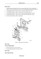
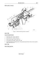
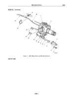
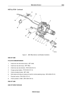
Figure 6.
ABS ECU Main Wiring Harness Installation.
END OF TASK
FOLLOW-ON MAINTENANCE
1.
Install battery switch. (Volume 2, WP
0310)
2.
Install starter switch. (Volume 2, WP
0310)
3.
Install instrument cluster. (Volume 2, WP
0310)
4.
Connect battery ground cables. (Volume 2, WP
0350)
5.
Start engine and allow air pressure to build to normal operating range. Road test vehicle and check operation
of ABS. (TM 9-2320-272-10)
END OF TASK
END OF WORK PACKAGE
TM 9-2320-272-23-3
0467
0467-9/10 blank
Back to Top

