TM-9-2320-272-23-3 - Page 951 of 1469
INSTALLATION
1.
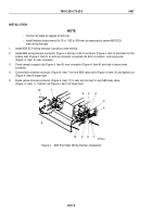
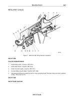
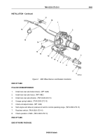
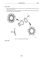
Position clamp (Figure 2, Item 11) on ABS wheel sensor lead (Figure 2, Item 18).
2.
Push sensor clip (Figure 2, Item 6) into ABS wheel sensor bracket (Figure 2, Item 3) until clip tabs
(Figure 2, Item 7) make contact with inner edge of ABS wheel sensor bracket.
3.
Push ABS wheel sensor (Figure 2, Item 8) into sensor clip (Figure 2, Item 6) until shoulder on sensor makes
contact with clip tabs (Figure 2, Item 7).
NOTE
Position ABS wheel sensor bracket on brake spider with ABS wheel sensor lead coming out
the groove at the top of sensor bracket.
4.
Position ABS wheel sensor lead (Figure 2, Item 18) in groove on ABS wheel sensor bracket (Figure 2, Item 3)
and install bracket on rear brake spider (Figure 2, Item 2) with two washers (Figure 2, Item 5), screws
(Figure
2,
Item
4), washers (Figure 2, Item 5), and locknuts (Figure 2, Item 14). Tighten screws
110
to
145
lb-ft (149 to 196 N·m).
5.
Install rubber plug (Figure 2, Item 12) on ABS wheel sensor lead (Figure 2, Item 18).
6.
Route ABS wheel sensor lead (Figure 2, Item 18) through hole in dust cover (Figure 2, Item 1) and install clamp
(Figure 2, Item 11) on rear brake spider (Figure 2, Item 2) with washer (Figure 2, Item 10), screw
(Figure 2, Item 9), washer (Figure 2, Item 10), and locknut (Figure 2, Item 13). Tighten screw
110 to 145 lb-ft (149 to 196 N·m).
7.
Route ABS wheel sensor lead (Figure 2, Item 18) over to ABS wiring harness A2 blue lead (Figure 2, Item 16),
positioning lead on rear side of axle housing, and secure with tiedown straps (Figure 2, Item 15).
8.
Connect ABS wheel sensor lead (Figure 2, Item 18) to ABS wiring harness A2 blue lead (Figure 2, Item 16)
and install leads in 3-way clip (Figure 2, Item 17) with two tiedown straps (Figure 2, Item 15).
TM 9-2320-272-23-3
0468
0468-4
Back to Top

