TM-9-2320-272-23-3 - Page 960 of 1469
REMOVAL - Continued
4.
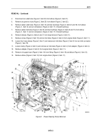
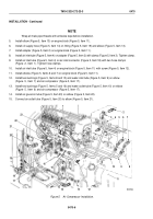
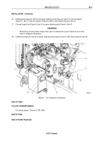
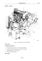
Disconnect air outlet tube (Figure 2, Item 20) from elbow (Figure 2, Item 21).
5.
Remove air governor tube (Figure 2, Item 23) from elbow (Figure 2, Item 22).
6.
Remove water outlet tube (Figure 2, Item 10) and two bushings (Figure 2, Items 5 and 16) from elbow
(Figure
2,
Item
6) and air compressor (Figure 2, Item 17). Discard bushings.
7.
Remove water inlet tube (Figure 2, Item 9) and two bushings (Figure 2, Items 8 and 15) from elbow
(Figure
2,
Item
7) and air compressor (Figure 2, Item 17). Discard bushings.
8.
Remove elbows (Figure 2, Items 6 and 7) from engine block (Figure 2, Item 11).
9.
Remove screw (Figure 2, Item 12) and air inlet tube (Figure 2, Item 4) from engine block (Figure 2, Item 11).
10.
Loosen two hose clamps (Figure 2, Item 1) and remove air inlet tube (Figure 2, Item 4) from air inlet connector
(Figure 2, Item 18).
11.
Loosen clamp (Figure 2, Item 3) and remove air inlet tube (Figure 2, Item 4) from adapter (Figure 2, Item 2).
12.
Remove adapter (Figure 2, Item 2) from engine block (Figure 2, Item 11).
13.
Remove oil supply hose (Figure 2, Item 14) from fitting (Figure 2, Item 19) and elbow (Figure 2, Item 13).
14.
Remove elbow (Figure 2, Item 13) from engine block (Figure 2, Item 11).
M9683DAA
1
2
3
4
5
6
7
8
9
10
11
12
13
14
15
16
17
18
19
20
21
22
23
Figure 2.
Power Steering Pump Removal.
TM 9-2320-272-23-3
0470
0470-3
Back to Top

