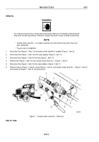
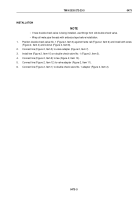
TM-9-2320-272-23-3 - Page 969 of 1469
INSTALLATION
NOTE
Male pipe threads must be wrapped with antiseize tape before installation.
1.
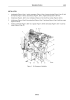
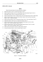
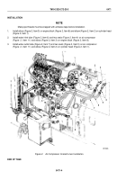
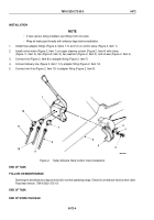
Install elbow (Figure 2, Item 3) on engine block (Figure 2, Item 8) and elbow (Figure 2, Item 2) on cylinder head
(Figure 2, Item 1).
2.
Install water inlet tube (Figure 2, Item 6) and two seals (Figure 2, Item 4) on air compressor
(Figure
2,
Item
11) and elbow (Figure 2, Item 3) on engine block (Figure 2, Item 8).
3.
Install water outlet tube (Figure 2, Item 7) and two seals (Figure 2, Item 5) on air compressor
(Figure
2,
Item
11) and elbow (Figure 2, Item 2) on cylinder head (Figure 2, Item 1).
M0130DAA
1
2
3
7
6
5
4
11
5
10
4
9
8
Figure 2.
Air Compressor Coolant Lines Installation.
END OF TASK
TM 9-2320-272-23-3
0471
0471-4
Back to Top

