TM-9-2320-272-23-3 - Page 967 of 1469
REMOVAL
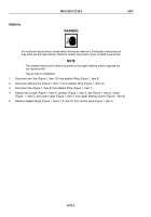
NOTE
When disconnecting water lines or hoses, plug ends and tag for identification
during
installation.
1.
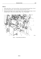
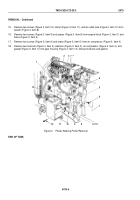
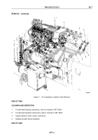
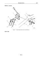
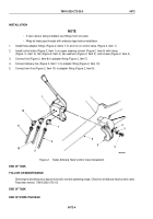
Disconnect two tubing nuts (Figure 1, Item 10) and remove water outlet tube (Figure 1, Item 7) and two seals
(Figure 1, Item 5) from air compressor (Figure 1, Item 11) and elbow (Figure 1, Item 2) in cylinder head
(Figure
1, Item 1). Discard seals.
2.
Disconnect two tubing nuts (Figure 1, Item 9) and remove water inlet tube (Figure 1, Item 6) and two seals
(Figure 1, Item 4) from air compressor (Figure 1, Item 11) and elbow (Figure 1, Item 3) in engine block
(Figure
1, Item 8). Discard seals.
3.
Remove elbow (Figure 1, Item 2) from cylinder head (Figure 1, Item 1) and elbow (Figure 1, Item 3) from engine
block (Figure 1, Item 8).
TM 9-2320-272-23-3
0471
0471-2
Back to Top

