TM-9-2320-272-23-4 - Page 1061 of 1393
REMOVAL - Continued
8.
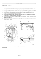
Remove eight locknuts (Figure 3, Item 6), screws (Figure 3, Item 7), and two rear holddown brackets
(Figure
3,
Item
5) from frame (Figure 3, Item 8). Discard locknuts.
9.
Attach two utility chains to frame channel (Figure 3, Item 4).
10.
Attach lifting device to center of two utility chains and remove slack from utility chain.
11.
Remove two cotter pins (Figure 3, Item 11), slotted nuts (Figure 3, Item 12), washer (Figure 3, Item 13), screws
(Figure 3, Item 18), upper half-keeper (Figure 3, Item 17), spring (Figure 3, Item 16), and lower half-keeper
(Figure 3, Item 15) from two front holddown brackets (Figure 3, Item 14) and frame (Figure 3, Item 8). Discard
cotter pins.
12.
Connect two guide lines (Figure 3, Item 10) to front and rear of subframe (Figure 3, Item 1).
WARNING
All personnel must stand clear during lifting operations. A snapped chain, or shifting or
swinging load, may result in injury to personnel. Failure to comply may result in injury or death
to personnel.
NOTE
Mechanic will handle one guide line and direct hoisting operation. Assistant will handle other
guide line. Second assistant will operate lifting device.
13.
Lift subframe (Figure 3, Item 1) clear of frame (Figure 3, Item 8) and place on two shop stands
(Figure 3, Item 9).
14.
Remove guide lines, lifting device, and utility chains from subframe (Figure 3, Item 1).
TM 9-2320-272-23-4
0717
0717-6
Back to Top

