TM-9-2320-272-23-5 - Page 171 of 623
REMOVAL
WARNING
Dump body must be raised and secured with safety braces before removal and installation
of chafe guard kit. Failure to comply may result in injury or death to personnel.
CAUTION
Plug all hydraulic openings and hoses to prevent contamination.
NOTE
Tag all hoses and tubes for proper installation.
1.
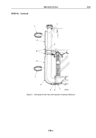
Disconnect hoses (Figure 1, Items 4 and 5) from elbows (Figure 1, Items 21 and 22).
2.
Remove hoses (Figure 1, Items 4 and 5) and o-rings (Figure 1, Item 6) from safety lock cylinder
(Figure
1,
Item 7). Discard o-rings.
3.
Remove hoses (Figure 1, Items 1 and 2) from crosses (Figure 1, Items 3 and 20).
4.
Remove hoses (Figure 1, Items 9, 10, 17, and 18) from four connectors (Figure 1, Item 14).
5.
Remove four connectors (Figure 1, Item 14) from four cylinder ports (Figure 1, Items 12, 13, 15, and 16).
6.
Remove two locknuts (Figure 1, Item 11), plate (Figure 1, Item 8), cross (Figure 1, Item 3), plate
(Figure
1,
Item 8), cross (Figure 1, Item 20), and plate (Figure 1, Item 8) from two screws (Figure 1, Item 19).
Discard locknuts.
7.
Remove hoses (Figure 1, Items 10 and 17) from cross (Figure 1, Item 3).
8.
Remove hoses (Figure 1, Items 9 and 18) from cross (Figure 1, Item 20).
9.
Remove elbows (Figure 1, Items 21 and 22) from crosses (Figure 1, Items 3 and 20).
TM 9-2320-272-23-5
0785
0785-2
Back to Top


