TM-9-2320-272-23-5 - Page 175 of 623
INSTALLATION - Continued
3.
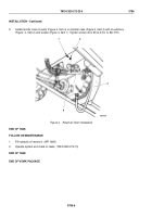
Install elbows (Figure 4, Item 21 and 22) on crosses (Figure 4, Item 3 and 20).
4.
Install hoses (Figure 4, Items 9 and 18) on cross (Figure 4, Item 20).
5.
Install hoses (Figure 4, Items 10 and 17) on cross (Figure 4, Item 3).
6.
Install plate (Figure 4, Item 8), cross (Figure 4, Item 20), plate (Figure 4, Item 8), cross (Figure 4, Item 3), plate
(Figure 4, Item 8), and two locknuts (Figure 4, Item 11) on screws (Figure 4, Item 19).
7.
Install four connectors (Figure 4, Item 14) on cylinder ports (Figure 4, Items 12, 13, 15, and 16).
8.
Install hoses (Figure 4, Items 9, 10, 17, and 18) on connectors (Figure 4, Item 14).
9.
Install hoses (Figure 4, Items 1 and 2) on crosses (Figure 4, Items 3 and 20).
10.
Install two o-rings (Figure 4, Item 6) and hoses (Figure 4, Items 4 and 5) on safety lock cylinder
(Figure
4,
Item 7).
11.
Connect hoses (Figure 4, Items 4 and 5) to elbows (Figure 4, Items 21 and 22).
TM 9-2320-272-23-5
0785
0785-6
Back to Top


