TM-9-2320-272-23-5 - Page 182 of 623
INSTALLATION
NOTE
Apply antiseize to all male pipe threads before installation.
1.
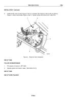
Position pipe nipple (Figure 3, Item 2) in hydraulic reservoir (Figure 3, Item 1) and install Y-branch
(Figure
3,
Item 4) to pipe nipple (Figure 3, Item 2).
2.
Install reducer bushing (Figure 3, Item 6), pipe nipple (Figure 3, Item 7), ball valve (Figure 3, Item 8), and hex
plug (Figure 3, Item 9) on Y-branch (Figure 3, Item 4).
3.
Install adapter (Figure 3, Item 5) in Y-branch (Figure 3, Item 4).
4.
Connect reservoir hydraulic tube (Figure 3, Item 3) to adapter (Figure 3, Item 5).
M9854DAA
1
2
3
4
5
6
7
8
9
Figure 3.
Hydraulic Reservoir Drain Installation.
TM 9-2320-272-23-5
0786
0786-5
Back to Top


