TM-9-2320-272-23-5 - Page 188 of 623
INSTALLATION
NOTE
•
When applying pipe sealant to male threads, leave first two starter threads clear of sealing
compound before installing.
•
Sealing compound is not necessary on adapter assemblies with o-rings.
1.
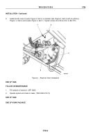
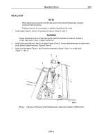
Install nipple (Figure 4, Item 3) on hydraulic oil reservoir (Figure 4, Item 4).
WARNING
Ensure directional arrow on check valve points toward the hydraulic oil reservoir. Failure to
comply may result in injury or death to personnel.
2.
Install check valve (Figure 4, Item 2) on nipple (Figure 4, Item 3). Ensure directional arrow on check valve
points toward hydraulic reservoir (Figure 4, Item 4).
3.
Install union assembly (Figure 4, Item 5) and hose assembly (Figure 4, Item 1) on check valve
(Figure
4,
Item
2).
M6294DAA
1
2
3
4
5
Figure 4.
Hydraulic Oil Reservoir Shutoff Modification Component Installation (M936/A1/A2).
TM 9-2320-272-23-5
0787
0787-5
Back to Top


