TM-9-2320-272-23-5 - Page 167 of 623
INSTALLATION - Continued
8.
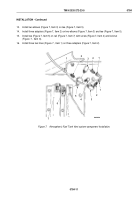
Install tubes (Figure 6, Items 6 and 9) on hose (Figure 6, Item 2) with two clamps (Figure 6, Item 8).
9.
Install tubes (Figure 6, Items 6 and 9) and hose (Figure 6, Item 2) on air intake pipe (Figure 6, Item 1) with four
clamps (Figure 6, Item 7).
10.
Install adapter (Figure 6, Item 5) on tube (Figure 6, Item 6).
11.
Install adapter (Figure 6, Item 4) on adapter (Figure 6, Item 5).
12.
Install vent line (Figure 6, Item 3) on adapter (Figure 6, Item 4).
3
M9860DAA
4
5
6
7
6
8
9
2
7
1
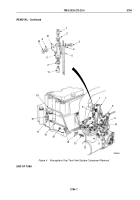
Figure 6.
Atmospheric Fuel Tank Vent System Component Installation.
TM 9-2320-272-23-5
0784
0784-10
Back to Top


