TM-9-2320-272-23-5 - Page 168 of 623
INSTALLATION - Continued
13.
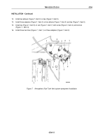
Install two elbows (Figure 7, Item 3) on tee (Figure 7, Item 5).
14.
Install three adapters (Figure 7, Item 2) on two elbows (Figure 7, Item 3) and tee (Figure 7, Item 5).
15.
Install tee (Figure 7, Item 5) on rail (Figure 7, Item 7) with screw (Figure 7, Item 4) and locknut
(Figure
7,
Item
6).
16.
Install three fuel lines (Figure 7 , Item 1) on three adapters (Figure 7, Item 2).
M9858DAA
5
4
3
2
1
1
2
3
2
1
6
7
Figure 7.
Atmospheric Fuel Tank Vent system component Installation.
TM 9-2320-272-23-5
0784
0784-11
Back to Top

