TM-9-2320-272-24-1 - Page 199 of 1015
TM 9-2320-272-24-1
Table 2-3. Electrical Troubleshooting (Contd).
MALFUNCTION
TEST OR INSPECTION
CORRECTIVE ACTION
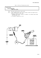
Test 4. Test voltage input to protective control box.
Step 1.
Set multimeter to 50-volt range.
Step 2.
Disconnect harness connector at protective control box.
Step 3.
Place battery switch to ON.
Step 4.
Connect multimeter positive lead to pin A (lead 459) at harness connector and negative
lead to ground.
a.
Multimeter should indicate voltage. If voltage is not indicated, repair broken lead
459 (para. 3-131).
b. If voltage is indicated, go to step 5.
Step 5.
Place battery switch to OFF position.
Step 6.
Connect multimeter positive lead to pin C (lead 81) at harness connector and negative
lead to ground.
a.
Multimeter should indicate voltage. If voltage is not indicated, repair broken lead 81
(para. 3-131).
b.
If voltage is indicated, go to test 5.
2-111
Back to Top


