TM-9-2320-272-24-2 - Page 544 of 991
TM 9-2320-272-24-2
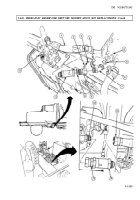
3-444. HYDRAULIC RESERVOIR DRAIN KIT REPLACEMENT
THIS TASK COVERS:
a. Removal
b. Installation
APPLICABLE MODELS
M929/A1, M930/A1
REFERENCES (TM)
TOOLS
TM 9-2320-272-10
TM 9-2320-272-24P
General mechanic’s tool kit (Appendix E, Item 1)
Torque wrench (Appendix E, Item 144)
EQUIPMENT CONDITION
Parking brake set (TM 9-2320-272-10).
Dump body raised and support braces in position
MATERIALS/PARTS
(TM 9-2320-272-10).
Teflon pipe sealant (Appendix C, Item 67)
Antiseize tape (Appendix C, Item 72)
Cap and plug set (Appendix C, Item 14)
GENERAL SAFETY INSTRUCTIONS
Dump body must be raised and secured with safety
braces.
Dump body must be raised and secured with safety braces before
working under dump body. Failure to do this may result in injury to
personnel.
CAUTION
Wrap or plug hydraulic line openings to prevent dirt entering
and causing damage.
Position of transfer case oil pump should be marked to align with
transfer case for installation. Improper alignment of transfer case
oil pump housing to transfer case may damage components.
NOTE
Steps 1 and 2 provide clearance for hydraulic reservoir drain
removal.
Have drainage container ready to catch oil.
1.
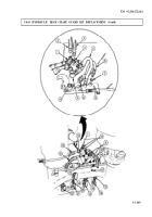
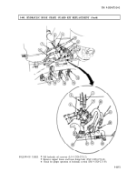
Remove six screws (1) and washers (2) from transfer case oil pump (4).
2.
Remove transfer case oil pump (4) from transfer case (3).
3.
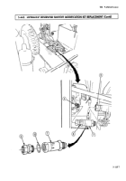
Disconnect reservoir hydraulic tube (7) from adapter (9).
4.
Remove adapter (9) from Y-branch (8).
5.
Remove hex plug (13), ball valve (12), pipe nipple (11), and reducer bushing (10) from Y-branch (8).
6.
Remove Y-branch (8) and pipe nipple (6) from hydraulic reservoir (5).
NOTE
Apply antiseize tape to all male threads prior to installation.
1.
Position pipe nipple (6) in hydraulic reservoir (5) and install Y-branch (8) to pipe nipple (6).
2.
Install reducer bushing (10), pipe nipple (11), ball valve (12), and hex plug (13) on Y-branch (8).
3.
Install adapter (9) in Y-branch (8).
3-1152
Back to Top

