TM-9-2320-272-24-2 - Page 540 of 991
TM 9-2320-272-234-2
3-443. HYDRAULIC HOSE CHAFE GUARD KIT REPLACEMENT
THIS TASK COVERS:
a. Removal
b. Installation
APPLICABLE MODELS
M929/A1/A2, M930/A1/A2
TOOLS
General mechanic’s tool kit (Appendix E, Item 1)
MATERIALS/PARTS
Two packings (Appendix D, Item 437)
Two locknuts (Appendix D, Item 294)
Tiedown strap (Appendix D, Item 694)
Sealant (Appendix C, Item 62)
Cap and plug set (Appendix C, Item 14)
REFERENCES (TM)
LO 9-2320-272-12
TM 9-2320-272-10
TM 9-2320-272-24P
EQUIPMENT CONDITION
Parking brake set (TM 9-2320-272-10).
Dump body raised and support braces in position
(TM 9-2320-272-10).
Drain hydraulic oil reservoir (LO 9-2320-272-12).
GENERAL SAFETY INSTRUCTIONS
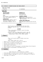
Dump body must be raised and secured with safety
braces.
Dump body must be raised and secured with safety braces before
removal and installation of chafe guard kit. Failure to do this may
result in injury to personnel.
Plug all hydraulic openings and hoses to prevent contamination.
1.
2.
3.
4.
5.
6.
7.
8.
9.
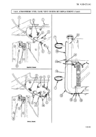
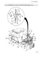
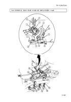
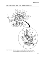
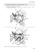
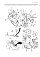
Remove elbows (9) and (10) from crosses (1) and (4).
NOTE
Tag all hoses and tubes for installation.
Disconnect hoses (5) and (6) from elbows (9) and (10).
Remove hoses (5) and (6) and packings (7) from safety lock cylinder (8). Discard packings (7).
Remove hoses (2) and (3) from crosses (1) and (4).
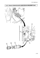
Remove hoses (11), (12), (16), and (15) from four connectors (20).
Remove four connectors (20) from four cylinder ports (18), (21), (19), and (22).
Remove hoses (11) and (16) from cross (4).
Remove hoses (12) and (15) from cross (1).
Remove two locknuts (17), plate (14), cross (4), plate (14), cross (1), and plate (14) from two
screws (13). Discard locknuts (17).
3-1148
Back to Top

