TM-9-2320-272-24-2 - Page 546 of 991
TM 9-2320-272-24-2
3-445. HYDRAULIC RESERVOIR SHUTOFF MODIFICATION KIT REPLACEMENT
THIS TASK COVERS:
a. Removal
b. Installation
APPLICABLE MODELS
M936/A1/A2
TOOLS
General mechanic’s tool kit (Appendix E, Item 1)
Torque wrench (Appendix E, Item 146)
MATERIALS/PARTS
Two O-rings (Appendix D, Item 489)
O-ring (Appendix D, Item 490)
Sealing compound (Appendix C, Item 63)
REFERENCES (TM)
LO
9-2320-272-12
TM
9-2320-272-20
TM
9-2320-272-24P
EQUIPMENT CONDITION
Battery ground cables disconnected (para. 3-1261.
Forward deck plate removed (para. 3-392).
Hydraulic oil reservoir drained (LO 9-2320-272-12).
GENERAL SAFETY INSTRUCTIONS
Directional arrow on check valve must point toward
hydraulic reservoir. Failure may result in personnel
injury and damage to equipment.
NOTE
Have drainage container ready to catch oil.
1.
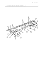
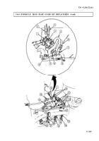
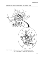
Remove hose assembly (1) from check valve (10) and adapter (11).
2.
Remove check valve (10), O-ring (9), and adapter assembly (8) from adapter (7). Discard O-ring (9).
3.
Remove four screws (2), washers (3), two swivel flanges (4), adapter (7), and O-ring (6) from front
winch pump outlet port (5). Discard O-ring (6).
NOTE
From under wrecker pull hose assembly far enough to provide
clearance for check valve removal.
4.
Disconnect hose assembly (13) from check valve (14).
5.
Remove adapter assembly (15) and check valve (14) from elbow (12).
3-1154
Back to Top

