TM-9-2320-272-24-2 - Page 676 of 991
TM 9-2320-272-24-2
3-470. CTIS WIRING HARNESS REPLACEMENT
THIS TASK COVERS:
a. Removal
b. Installation
INITIAL SETUP:
APPLICABLE MODELS
REFERENCES (TM)
M939A2
TM 9-2320-272-10
TOOLS
TM 9-2320-272-24P
General mechanic’s tool kit (Appendix E, Item 1)
EQUIPMENT CONDITION
MATERIALS/PARTS
l
Parking brake set (TM 9-2320-272-10).
Grommet (Appendix D, Item 252)
l
Battery ground cables disconnected (para. 3-126).
Tiedown straps (Appendix D, Item 690)
a. Removal
1.
2.
3.
4.
5.
6.
7.
8.
9.
10.
11.
12.
13.
NOTE
l
When removing CTIS wiring harness, note location of all
tiedown straps and protective covering for installation.
l
Tag all wiring harness leads and note routing for installation.
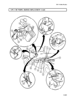
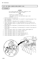
Disconnect wiring harness connector (12) from ECU receptacle (9).
Disconnect wiring harness connector (10) from amber warning light wire (11).
Disconnect wiring harness connector (18) from power and ground cable (17).
Disconnect wiring harness connector (15) from blackout wire (16).
Disconnect wiring harness connector (20) from pressure transducer (19).
Disconnect wiring harness connector (22) from pneumatic controller solenoid receptacle (21).
Disconnect wiring harness connector (1) from speed signal generator wire (23) on transfer case (5).
Disconnect wire (4) from pressure switch wire (24) located on right frame rail (2) above wet
tank (3).
Remove screw (26), washer (27), and clamp (28) from wiring harness (7) and bracket (25).
Remove screw (30), washer (29), and clamp (31) from wiring harness (7) and firewall (13).
Remove wiring harness (7) from frame rails (2) and (8) and crossmember (6).
Carefully pull wiring harness (7) through grommet (14) on firewall (13).
NOTE
Perform step 13 if grommet is damaged.
Remove grommet (14) from firewall (13). Discard grommet (14).
3-1284
Back to Top

