TM-9-2320-272-24-2 - Page 670 of 991
TM 9-2320-272-24-2
3-466. WATER SEPARATOR MAINTENANCE
THIS TASK COVERS:
a. Removal
d. Assembly
b. Disassembly
e. Installation
c. Cleaning and Inspection
INITIAL SETUP:
APPLICABLE MODELS
M939A2
TOOLS
General mechanic’s tool kit (Appendix E, Item 1)
MATERIALS/PARTS
Fluid pressure kit (Appendix 128)
Crease (Appendix C, Item 32)
REFERENCES (TM)
TM 9-2320-272-10
TM 9-2320-272-24P
EQUIPMENT CONDITION
Parking brake set (TM 9-2320-272-10).
Air reservoirs drained (TM 9-2320-272-10).
GENERAL SAFETY INSTRUCTIONS
When cleaning with compressed air, wear eyeshields
and ensure source pressure does not exceed 30 psi
(207 kPa).
a. Removal
1.
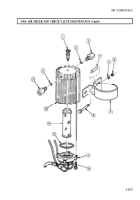
Disconnect two air lines (1) from adapters (2) on water separator (3).
2.
Remove two adapters (2) from water separator (3).
b. Disassembly
1.
Remove body (4) from bowl (12).
2.
Remove stud (9), filter (8), louver (7), gasket (6), and O-ring (5) from body (4). Discard
filter (8), gasket (6), and O-ring (5).
3.
Remove automatic drain valve (10) and O-ring (11) from bowl (12). Discard O-ring (11).
c. Cleaning and Inspection
1.
For general inspection instructions, refer to para. 2-15.
2.
Clean bowl (12) with warm water and all other parts with soap and warm water.
WARNING
Eyeshields must be worn when cleaning with compressed air.
Compressed air source will not exceed 30 psi (207 kPa). Failure to
do so may result in injury to personnel.
3.
From inside body (4), blow out internal passages with compressed air.
d. Assembly
1.
Coat lip of automatic drain valve (10) with grease and install new O-ring (11) and automatic drain
valve (10) in bowl (12).
2.
Install new O-ring (5), new gasket (6), louver (7), and new filter (8) on body (4) with stud (9).
3.
Install body (4) on bowl (12).
3-1278
Back to Top


