TM-9-2320-272-24-3 - Page 218 of 799
TM 9-2320-272-24-3
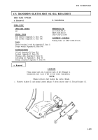
4-73. TRANSMISSION SELECT LEVER REPLACEMENT
THIS TASK COVERS:
a. Removal
b. Installation
INITIAL SETUP:
APPLICABLE MODELS
All
REFERENCES (TM)
TM 9-2320-272-10
TOOLS
TM 9-2320-272-24P
General mechanic’s tool kit (Appendix E, Item 1)
EQUIPMENT CONDITION
MATERIALS/PARTS
l
Parking brake set (TM 9-2320-272-10).
l
Battery ground cables disconnected (para. 3-126).
Four lockwashers (Appendix D, Item 345)
a. Removal
1.
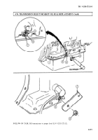
Remove four screws (15) and lockwashers (16) from control lever console (17). Discard lock-
washers (16).
2.
Pull select lever assembly (18) away from control lever console (17).
NOTE
Tag leads for installation.
3.
Disconnect three leads (14) from harness leads (13).
4.
Remove two nuts (12), cable clamp (11), shim (9), two screws (7), and washers (8) from hanger
plate (6).
5.
Remove spring clip (2) and pull trunnion (3) and shift cable (10) from selector lever plate (5).
6.
Remove selector lever assembly (18) from vehicle.
b. Installation
NOTE
Vehicle must be started in N (neutral) to check selector lever
assembly. Vehicle will start if installation is correct. Remove and
reinstall selector lever assembly if vehicle fails to start in N
(neutral).
1.
Place selector lever (1) in neutral position.
2.
Place manual control linkage arm (19) in neutral position. Linkage arm (19) will be one detent down
from full up position.
3.
Install shim (9), shift cable (10), and cable clamp (11) on hanger plate (6) with two washers (8),
screws (7), and nuts (12). Ensure cable clamp (11) seats in groove of shift cable (10) housing.
4.
Loosen jamnut (4) and align cable trunnion (3) with first hole above elongated slot in selector lever
plate (5). Cable trunnion (3) is turned clockwise to shorten and counterclockwise to lengthen.
Tighten jamnut (4) and install in plate (5) with spring clip (2).
5.
Connect three electrical leads (14) to harness leads (13).
6.
Install selector lever assembly (18) in control lever console (17) with four new lockwashers (16) and
screws (15).
4-482
Back to Top

