TM-9-2320-272-24-3 - Page 22 of 799
TM 9-2320-272-24-3
4-41. ROCKER LEVERS, PUSH RODS, AND CYLINDER HEAD REPLACEMENT (Contd)
c. Cylinder Head Installation
NOTE
Cylinder head assemblies are interchangeable between early
model engines, 44487830 and before, and late model engines,
after 44487830. When interchanging cylinder head assemblies,
3913111, early model engines, and 3917767, late model engines,
ensure the corresponding cylinder head screws are used and air
compressor plumbing matches the applicable engine model
configuration.
Perform step 1 if installing new late model cylinder head.
1.
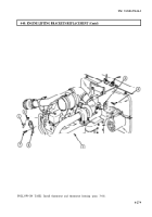
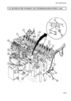
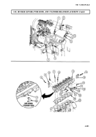
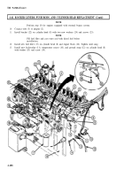
Install coupling (19) on cylinder head (6).
2.
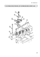
Install lifting brackets (2) and (8) on cylinder head (6) with two screws (1) and (7).
3.
Install new washer (10), plug (11), elbow (12), adapters (3), (13), and (14), atomizer (18),
adapter (17), and nipple (9) on cylinder head (6).
NOTE
Assistant will help with step 4.
4.
Position new gasket (15) and cylinder (6) on engine block (16) and install with fourteen screws (4)
and twelve screws (5).
NOTE
Perform step 5 for late model engines.
Perform step 6 for early model engines.
5.
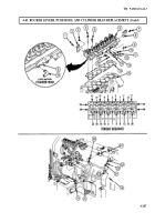
Tighten screws (4) and (5) using the following steps:
a. Tighten screws (4) and (5) in sequence shown.
b. Loosen screws (4) and (5) in sequence shown.
c. Tighten screws (4) and (5) 50 lb-ft (68 N·m) in sequence shown.
d. Tighten long screws (4) 105 lb-ft (142 N·m) in sequence shown.
e. Using torque angle gauge, rotate screws (4) and (5) an additional 75-105 degrees in sequence
shown.
6.
Tighten screws (4) and (5) using the following steps:
a. Tighten screws (4) and (5) 30 lb-ft (41 N·m) is sequence shown.
b. Tighten screws (4) and (5) 110 lb-ft (149 N·m) in sequence shown.
c. Tighten screws (4) and (5) 160 lb-ft (217 N·m) in sequence shown.
7.
Connect air supply tube (25) to coupling (21) with clamp (20).
8.
Install air supply tube (25) on engine block (16) with screw (26).
9.
Install new seal (23) and water inlet tube (24) on elbow (22).
4-286
Back to Top

