TM-9-2320-272-24-3 - Page 28 of 799
TM 9-2320-272-24-3
4-43. FLEXPLATE AND FLYWHEEL HOUSING MAINTENANCE
THIS TASK COVERS:
a. Removal
d. Assembly
b. Disassembly
e. Installation
c. Cleaning and Inspection
INITIAL SETUP:
APPLICABLE MODELS
M939A2
PERSONNEL REQUIRED
Two
SPECIAL TOOLS
REFERENCES (TM)
Engine barring tool (Appendix E, Item 43)
TOOLS
General mechanic’s tool kit (Appendix E, Item 1)
Torque wrench (Appendix E, Item 144)
MATERIALS/PARTS
Seal (Appendix D, Item 602)
Gasket (Appendix D, Item 189)
Antiseize tape (Appendix C, Item 72)
Gasket sealant (Appendix C, Item 30)
Lubricating oil (Appendix C, Item 50)
TM 9-2320-272-24P
EQUIPMENT CONDITION
Transmission (out-of-vehicle) removed (para. 4-72).
CAUTION
Do not use timing pin to prevent engine from turning. Doing so
may cause damage to timing pin.
NOTE
Assistant will help with this procedure.
a. Removal
1.
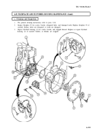
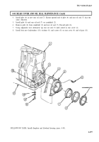
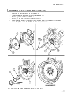
Using engine barring tool, prevent crankshaft (13) from turning.
2.
Remove eight screws (7), clamping ring (8), flexplate (9), and crankshaft adapter (6) from
crankshaft (13).
3.
Remove twelve screws (5), flywheel housing (4), and seal (3) from rear cover (14). Discard seal (3).
NOTE
Perform step 4 if dowel pins are damaged.
4.
Remove two dowel pins (2) from engine block (1).
b. Disassembly
1.
Remove two pipe plugs (18) from flywheel housing (4).
2.
Remove two screws (15), cover plate (16), and gasket (17) from flywheel housing (4). Discard
gasket (17).
NOTE
Tag mounting brackets for installation. One on each side of
flywheel housing. One side shown.
3.
Remove eight screws (12), washers (11), and two mounting brackets (10) from flywheel housing (4).
4-292
Back to Top

