TM-9-2320-272-24-3 - Page 26 of 799
TM 9-2320-272-24-3
4-42. VIBRATION DAMPER MAINTENANCE
THIS TASK COVERS:
a. Removal
b. Inspection
c. Installation
INITIAL SETUP:
APPLICABLE MODELS
M939A2
SPECIAL TOOLS
REFERENCES (TM)
Engine barring tool (Appendix E, Item 43)
TOOLS
General mechanic’s tool kit (Appendix E, Item 1)
Torque wrench (Appendix E, Item 144)
MATERIALS/PARTS
O-ring (Appendix D, Item 444)
PERSONNEL REQUIRED
Two
TM 9-2320-272-10
TM 9-2320-272-24P
EQUIPMENT CONDITION
Parking brake set (TM 9-2320-272-10).
Engine drivebelt removed (para. 3-71).
Fan and fan shroud removed (para. 3-64).
NOTE
Assistant will help with this procedure.
a. Removal
1.
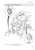
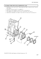
Remove plug (4) and O-ring (3) from flywheel housing (2). Discard O-ring (3).
2.
Using engine barring tool, prevent crankshaft (1) from turning.
3.
Remove four screws (6) and vibration damper (5) from crankshaft (1).
b. Inspection
1.
Inspect vibration damper (5) for bends, breaks, and damaged pulley grooves. Replace vibration
damper (5) if bent, broken, or grooves are damaged.
2.
Inspect vibration damper alignment marks (8). Replace vibration damper (5) if alignment
marks (8) are 0.063 in. (1.60 mm) out of alignment.
3.
Inspect rubber member (7) for wear and damage. Replace vibration damper (5) if damaged or worn
more than 0.125 in. (3.18 mm) deeper than face of vibration damper (5).
c. Installation
1.
Using engine barring tool, prevent crankshaft (1) from turning.
2.
Install vibration damper (5) on crankshaft (1) with four screws (6). Tighten screws (6) 150 lb-ft
(203 N·m).
3.
Install new O-ring (3) and plug (4) in flywheel housing (2).
4-290
Back to Top

