TM-9-2320-272-24-3 - Page 326 of 799
TM 9-2320-2721-24-3
4-109. RELAY VALVE REPAIR
THIS TASK COVERS:
a. Disassembly
b. Cleaning and Inspection
c. Assembly
INITIAL SETUP
APPLICABLE MODELS
ALL
TOOLS
General mechanic’s tool kit (Appendix E, Item 1)
Torque wrench (Appendix E, Item 146)
MATERIALS/PARTS
Valve repair kit (Appendix D, Item 707)
Four lockwashers (Appendix D, Item 386)
Four lockwashers (Appendix D, Item 387)
Lint-free cloth (Appendix C, Item 21)
Lubricating oil (Appendix C, Item 48)
REFERENCES (TM)
TM 9-2320-272-24P
EQUIPMENT CONDITION
Relay valve removed (para. 3-187 or 3-188).
NOTE
Do not perform this procedure unless valve repair kit is available.
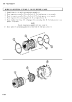
a. Disassembly
1.
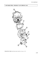
Scribe an alignment mark across valve cover (2) and valve body (1).
2.
Remove capnut (3), O-ring (4), and diaphragm (5) from valve cover (2). Discard O-ring (4) and
diaphragm (5).
3.
Remove four screws (6), lockwashers (7), and valve cover (2) from valve body (1). Discard lockwashers (7).
4.
Remove seal ring (10) from valve body (1). Discard seal ring (10).
5.
Remove relay piston (9) and O-ring (8) from valve cover (2). Discard O-ring (8).
6.
Scribe an alignment mark across exhaust cover (11) and valve body (1).
7.
Remove four screws (15), lockwashers (14), exhaust cover (11), gasket (12), and exhaust valve
assembly (13) from valve body (1). Discard lockwashers (14), gasket (12), and exhaust valve
assembly (13).
b. Cleaning and Inspection
1.
Clean valve cover (2), valve body (1), exhaust cover (11), and relay piston (9) with lint-free cloth.
2.
Inspect valve cover (2), valve body (1), exhaust cover (11), and relay piston (9) for cracks, breaks,
chips, and pitting. Discard part(s) if cracked, broken, chipped, and pitted.
1.
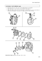
Install new exhaust valve assembly (13) in valve body (1). Use thumb pressure to seat properly.
2.
Align scribe marks on exhaust cover (11) and valve body (1) and install new gasket (12) and exhaust
cover (11) on valve body (1) with four new lockwashers (14) and screws (15). Tighten screws (15)
2-3 lb-ft (3-4 N•m).
3.
Apply lubricating oil on new O-ring (4) and install on capnut (3).
4.
Install new diaphragm (5) and capnut (3) on valve cover (2). Tighten capnut (3) 12 lb-ft (16 N•m).
5.
Apply lubricating oil to new O-ring (8) and install on relay piston (9).
4-590
Back to Top

