TM-9-2320-272-24-3 - Page 342 of 799
TM 9-2320-272-24-3
4-116. UPPER AND LOWER STEERING COLUMN MAINTENANCE
THIS TASK COVERS:
a. Removal
b. Disassembly
c. Cleaning, Inspection, and Repair
d. Reassembly
e. Installation
INITIAL SETUP:
APPLICABLE
MODELS
All
TOOLS
General mechanic’s tool kit (Appendix E, Item 1)
Torque wrench (Appendix E, Item 146)
MATERlALS/PARTS
Lockwasher (Appendix D, Item 354)
Two locknuts (Appendix D, Item 291)
PERSONNEL REQUIRED
TWO
REFERENCES (TM)
TM 9-2320-272-10
TM 9-2320-272-24P
EQUIPMENT DESCRlPTlON
• Parking brake set (TM 9-2320-272-10).
• Steering wheel removed (para. 3-226).
• Horn wire disconnected (para. 3-104).
• Turn signal indicator switch removed (para. 3-113).
• Trailer airbrake hand control valve removed
(para. 3-210).
• Horn contact brush removed (para. 3-102).
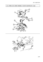
a. Removal
1.
2.
3.
4.
5.
6.
NOTE
Before removing steering wheel columns, make sure front wheels
are straight ahead for proper steering wheel alignment.
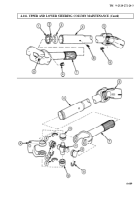
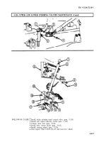
Remove nut (9), lockwasher (10), and screw (12) from universal joint (11). Discard lockwasher (10).
Remove two locknuts (14), screws (7), washers (8), and lower mounting clamp (6) from upper
steering column (3) and firewall (13). Discard locknuts (14).
NOTE
Mark upper support clamp location on steering column for
installation.
Remove two screws (5) and upper support clamp (4) from upper steering column (3) and instrument
panel (1).
Remove upper steering column (3) from universal joint (11) and lift out through floorboard (15).
Slide two clamp bushings (2) off upper steering column (3).
Remove nut (16), lockwasher (17), and screw (19) and U-joint (18) from steering gear input shaft (20).
Discard lockwasher (17).
4-606
Back to Top

