TM-9-2320-272-24-3 - Page 350 of 799
TM 9-2320-272-24-3
4-117. STEERING GEAR (ROSS) AND MOUNTING BRACKET REPLACEMENT
THIS TASK COVERS:
a. Removal
b. Installation
INITIAL SETUP:
APPLICATION MODELS
M939/A1
LO 9-2320-272-12
TOOLS
TM 9-2320-272-10
General mechanic’s tool kit (Appendix E, Item 1)
Torque wrench (Appendix E, Item 145)
Mechanical puller (Appendix E, Item 110)
MATERIALS/PARTS
Four locknuts (Appendix D, Item 294)
Two O-rings (Appendix D, Item 437)
O-ring (Appendix D, Item 477)
Lockwasher (Appendix D, Item 382)
Locknut (Appendix D, Item 273)
Cap and plug set (Appendix C, Item 14)
Antiseize tape (Appendix C, Item 72)
REFERENCES (TM)
TM
9-2320-272-24P
EQUIPMENT CONDITION
Parking brake set (TM 9-2320-272-10).
Left splash shield removed (para. 3-301).
Steering gear stone shield removed (para. 3-238).
Drag link removed (para. 3-229).
CAUTION
Cap or plug all openings immediately after disconnecting lines
and hoses to prevent contamination. Failure to do so may result
in power steering gear damage.
NOTE
Identify type of power steering gear. Removal and installation
are different for the two steering gears. Refer to section II,
chapter 1 and general information (para. 4-115).
Ensure front wheels are straight ahead.
1.
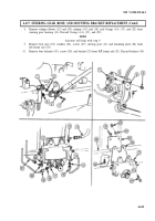
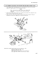
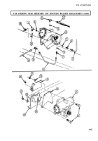
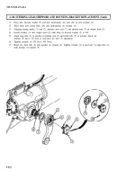
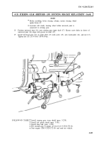
Remove nut (1), lockwasher (2), and screw (4) from U-joint (5) and steering gear input shaft (6).
Discard lockwasher (2).
2.
Open slot (3) in U-joint (5) and separate steering gear input shaft (6) and U-joint (5).
3.
Remove locknut (9) and screw (7) from pitman arm (10). Discard locknut (9).
NOTE
Punch alignment marks on pitman arm and sector shaft.
4.
Using a chisel, spread slot in top of pitman arm (10).
5.
Using a puller, remove pitman arm (10) from sector shaft (8).
NOTE
Have container ready to catch oil from disconnected lines.
Tag lines and fittings for installation
6.
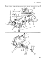
Disconnect oil pressure line (13) and oil return line (16) from adapter elbow (12) and adapter (15).
7.
Disconnect assist cylinder pressure lines (19) and (21) from adapter (18) and adapter elbow (20).
4-614
Back to Top


