TM-9-2320-272-24-3 - Page 354 of 799
4-118. STEERING GEAR (SHEPPARD) AND MOUNTING BRACKET REPLACEMENT
THIS TASK COVERS
a. Removal
b. Installation
INITIAL SETUP
APPLICABLE MODELS
M939A2
TOOLS
General mechanic’s tool kit (Appendix E, Item 1)
Torque wrench (Appendix E, Item 145)
MATERIALS/PARTS
Lockwasher (Appendix D, Item 382)
Four locknuts (Appendix D, Item 316)
Steering parts kit (Appendix D, Item 677)
Gasket and seal kit (Appendix D, Item 247)
Four locknuts (Appendix D, Item 294)
Four O-rings (Appendix D, Item 437)
Cap and plug set (Appendix C, Item 14)
Antiseize tape (Appendix C, Item 72)
REFERENCES (TM)
LO 9-2320-272-12
TM 9-2320-272-10
TM 9-2320-272-24P
EQUIPMENT DESCRIPTION
Parking brake set (TM 9-2320-272-10).
Left splash shield removed (para. 3-301).
Steering gear stone shield removed (para. 3-238).
Drag link disconnected (para. 3-229).
NOTE
Identify type of power steering gear. Removal and installation is
different for the two steering gears. Refer to chapter 1, section II
for identification.
Ensure front wheels are aligned straight ahead.
1.
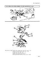
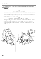
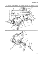
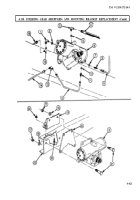
Remove nut (l), lockwasher (2), and screw (6) from sleeve (7) of universal joint (5). Discard
lockwasher (2).
2.
Using a chisel, open slot (3) in sleeve (7) of universal joint (5) and pull lower steering column (4) off
steering gear input shaft (8).
3.
Bend two long tabs (12) of retainer (11) out of notches in pitman arm (10).
4.
Bend two short tabs (13) out of retainer (11) and remove retainer (11) from sector shaft (15). Discard
retainer (11).
NOTE
Punch alignment marks on sector shaft and pitman arm.
5. Using puller, remove pitman arm (10) and seal (14) from sector shaft (15) of steering gear (9).
Discard seal (14).
4-618
TM 9-2320-272-24-3
Back to Top

