TM-9-2320-272-24-3 - Page 528 of 799
TM 9-2320-272-24-3
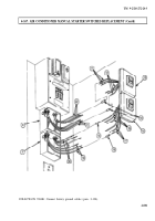
4-163. ELECTRICAL JUNCTION BOX REPLACEMENT
THIS TASK COVERS:
a. Removal
b. Installation
INITIAL SETUP:
APPLICABLE MODELS
MANUAL REFERENCES (TM)
M934/A1/A2
TM 9-2320-272-10
TOOLS
TM 9-2320-272-24P
TM 9-237
General mechanic’s tool kit (Appendix E, Item 1)
EQUIPMENT CONDITION
MATERIALS/PARTS
l
Parking brake set (TM 9-2320-272-10).
Eight locknuts (Appendix D, Item 318)
Sealing compound (Appendix C, Item 65)
l
Battery ground cables disconnected (para. 3-126).
a. Removal
1.
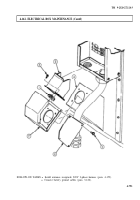
Remove two cables (3) from connectors (1).
2.
Remove eight screws (4) and cover (5) from junction box
NOTE
(7).
Tag wires for installation.
3.
Remove harness leads (6) and (8) from two connectors (1) (refer to TM 9-237).
4.
Remove eight locknuts (9), screws (2), and two connectors (1) from cover (5). Discard locknuts (9).
5.
Remove special nut (14), nut (15), adapter (13), and nut (12) from junction box (7).
6.
Remove junction box (7) from conduits (10) and (11) and slide off wires (6) and (8).
b. Installation
1.
Place nut (15) on conduit (10).
2.
Feed harness leads (6) and (8) through holes in junction box (7).
3.
Position junction box (7) on conduits (10) and (11).
4.
Install nut (15) on junction box (7)
5.
Feed conduit (11) through nut (12), adapter (13), junction box (7), and special nut (14).
6.
Install special nut (14) on junction box (7).
7.
Install two connectors (1) on cover (5) with eight screws (2) and locknuts (9).
8.
Connect harness leads (6) and (8) to two connectors (1) (TM 9-237).
9.
Coat edge of cover (5) with sealing compound and install cover (5) on junction box (7) with eight
screws (4).
10.
Connect two cables (3) to connectors (1).
4-792
Back to Top


