TM-9-2320-272-24-3 - Page 670 of 799
4-199. CRANE
TM 9-2320-272-24-3
THIS TASK COVERS:
a Removal
b. Installation
INITIAL SETUP:
APPLICABLE MODELS
REFERENCES (TM)
M936/A1/A2
LO 9-2320-272-12
TOOLS
TM 9-2320-272-10
General mechanic’s tool kit (Appendix E Item 1)
TM 9-2320-272-24P
Torque wrench (Appendix E, Item 144)
EQUIPMENT CONDITION
MATERIALS/PARTS
Parking brake set (TM 9-2320-272-10).
Four lockwashers (Appendix D, Item 377)
Cap and plug set (Appendix C, Item 14)
CAUTION
When disconnecting hydraulic lines, plug all openings to prevent
dirt from entering and causing internal damage to parts.
NOTE
Have drainage container ready to catch oil.
Tag all hydraulic flex lines and adapter elbows for installation.
1.
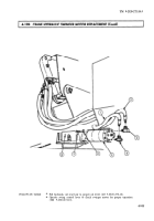
Disconnect hydraulic flex lines (1) and (2) from elbows (3) and (4).
2.
Remove four screws (7) and lockwashers (6) from swinger motor (5) and gearcase (8). Discard
lockwashers (6).
3.
Remove swinger motor (5) from gearcase (8).
4.
Remove elbows (3) and (4) from swinger motor (5).
1.
Install adapter elbows (3) and (4) on swinger motor (5).
2.
Install swinger motor (5) on gearcase (8) with four new lockwashers (6) and screws (7). Tighten
mews (7) 44-61 lb-ft (60-83 N•m).
3.
Connect hydraulic flex lines (1) and (2) to elbows (3) and (4).
4-934
Back to Top


