TM-9-2320-273-34 - Page 702 of 801
TM9-2320-273-34
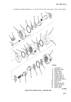
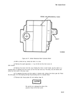
(6) Check the inside gear pockets of the body(l I)for excessive scoring and wear. If there are
grooves which would allow leakage past the ends of the gear teeth, the body must be replaced.
(7) It is not necessary to inspect the seals or thrust plates for wear. These parts must be re-
placed each time the pump is disassembled.
c. Assembly.
(1)
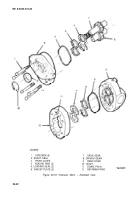
Install the shaft seal (3) in the front cover (4). Using a seal driver (a socket with an outside
diameter of approximately 1-5/8 inch works well) press the shaft seal in until the snapring groove is
barely exposed. Do not press further than is necessary to install the snapring as the seal will close off part
of the bearing drain hole. If this does occur, remove the seal and begin again.
(2)
Install the retaining ring (2) in the shaft seal cavity using truarc type snap ring pliers. Be
sure the retaining ring is completely seated in the groove.
(3) Install the
loading seals
(7)
in the seal groove in the front and rear cover and the adapter
section. Hold the seal in place over the groove and tap into the groove with a plastic mallet. Do not use
a steel hammer as it will dent the face of the cover and cause damage to the seals.
(4)
place sealing rings (6) in the grooves in the front and rear cover and adapter section.
(5)
Aline the scribed mark on the rear body with the scribed mark on the rear cover and
push down on the body to engage the dowel pins.
NOTE
It may be necessary to tap each dowel
alternately with a plastic mallet until
the body and rear cover are nearly together.
(6)
Lower one of the thrust plates (8) into the body (11) (flat side down) until the thrust
plate rests against the rear cover (15).
(7)
Insert the gears (14) and (9) into the rear body with the driven gear (14) nearest the
scribed mark on the rear body and rear cover.
(8)
Slide the second thrust plate over the ends of the gear shafts. The thrust plate must be
against the gears and not on the top surface.
(9) Aline the scribed mark on the adapter section and rear body. Push down on the adapter
section to engage the dowel pins.
Do not dislodge the seals in the adapter
section.
NOTE
it may be necessary to tap each dowel
alternately with a plastic mallet until the
body and adapter section are together.
20-19
CAUTION
Back to Top

