TM-9-2320-273-34 - Page 707 of 801
TM 9-2320-273-34
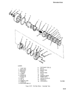
(6)
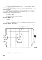
Lower one of the thrust plates into the body (flat side down) until the thrust plate rests
against the rear cover.
(7)
Insert the gears into the body with the drive gear nearest the scribed mark on the body and
rear cover.
(8)
Slide the second thrust plate over the ends of the gear shafts. The thrust plate must be
against the gears and not resting on the top surface.
(9)
Lubricate the keyed or splined end of the drive shaft so the shaft seal will slide over the
chamber on the shaft without damage.
(10)
Slide the front plate down onto the shafts and tap lightly with a plastic mallet to engage
the dowel pins. Be sure the scribed line is continuous across the front cover, body and rear cover.
(11)
Install the eight capscrews and tighten even to 35-40 Ib-ft (47-54 N-m) torque.
(12)
Rotate the shaft to be sure that the gears will be free to turn when the motor is mounted.
NOTE
The motor will have a slight amount of
drag but should turn freely after a short
period of use.
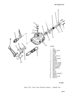
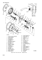
20-6. Repair of Control Valve (Speed Control).
a. Removal. (Refer
to TM 9-2320-273-20.)
b. Disassembly.
(1)
Clean the outside of the valve thoroughly.
(2)
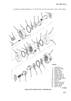
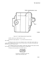
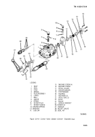
Clamp the valve body (1, fig. 20-19) in a vise.
20-24
Back to Top

