TM-9-2320-273-34 - Page 713 of 801
TM 9-2320-273-34
(2)
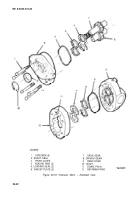
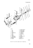
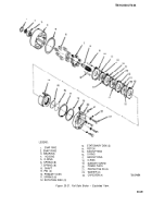
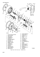
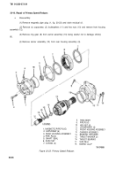
Alternately remove capscrews (23) and washers (22). Lift off the following:
(a)
(b)
(c)
(d)
(e)
(f)
(g)
(h)
Power plate (20)
O-ring (5)
Stationary disks (13)
Springs (11 )
Rotating disks (12)
Primary disk (10)
Pins (9)
Springs (6) and (7)
(3)
Remove snaprings (1) and (2).
(4)
Remove shaft (8) with attached bearing (3) by lightly tapping the shaft with a plastic
mallet.
(5)
Separate shaft (8) and bearing (3) by supporting the bearing inner race and applying
pressure to the shaft.
(6)
Remove piston (14) from power plate (20) by introducing low air pressure – approx-
imately 15 psi – into hydraulic inlet port, Make sure piston is pointing away from you.
NOTE
In step
(7),
do not remove backup
rings (15) and (17) unless replacement
is planned.
(7)
Remove O-rings (16) and (18) and backup rings (15) and (17) from piston (14).
b. Assembly.
(1)
Make sure that all parts are clean and dry. Use drycleaning solvent for cleaning.
(2)
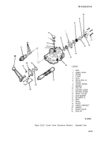
Apply a light coat of hydraulic oil on new O-rings (16) and (18) and install in piston (14).
(3)
If removed, install new backup rings (15) and (17).
(4)
Assemble piston (14) into power plate (20) using a shop press, being careful not to
damage the O-rings or Teflon backup rings. Visually aline the center of the cut-outs in the piston with
the n (9) holes in the power plate (20).
(5)
press bearing (3) on shaft (8) and install into housing (4). Secure with snap rings (1) and
(2).
(6)
Install O-ring (5) in housing (4).
(7) Install springs (6) and (7).
20-30
Back to Top

