TM-9-2320-273-34 - Page 718 of 801
TM 9-2320-273-34
(e)
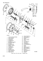
install each pinion shaft (21) into carrier and through each pinion gear (19). Aline
pinion shafts (21 ) to permit installation of retainer (12) on slot of shafts.
(f)
Apply Loctite (item 19, Appendix B) to threads of capscrews (14); then install
capscrews (14) and Iockwashers (13) to secure each retainer (12) to carrier. Tighten to 27-32 Ib-ft
(37-43 NŽm) torque.
(g)
Check end play of each pinion gear (19), Should be 0.004-0.020 in. If end play is
more than 0.020 in., replace thrust washers (17) and (20).
(h)
Check each pinion gear (19) to determine that it rotates freely, without binding or
restriction.
(6)
Insert the external spline shaft of secondary carrier (7) into sleeve bushing (1) from inside
of gear reduction support (39).
(7)
Install gasket (32) on gear support.
NOTE
In step
(8),
check to insure that ring gear
(38) fits pilot of support (39). If not,
reverse ring gear (38) and reinstall.
(8)
Install ring gear (38) over pinion gears in secondary carrier (7) and against face of support
(39). Aline holes for capscrews in ring gear (38) and support (39).
(9)
Install primary carrier (11 ) into ring gear (38). Rotate pinion gears (19) in primary car-
rier and sun gear (9) as necessary to engage teeth of ring gear and teeth of gears in secondary carrier (7).
(10)
Insert sun gear (15) into primary carrier (11).
(11)
Mount gasket (32) and cover (31) on ring gear (38); then install Iockwashers (29) and
capscrews (28). Tighten 85-95 lb-f-t (1 15-129 N•m) torque.
NOTE
In step
(12),
more than one gasket (23)
may be necessary to ensure that thrust
washer (24) has sufficient clearance for
installation.
(12)
Mount gasket (23), thrust washer (24) and cover (25) on cover (31), then install cap-
screws
(27)
and tighten to 20-25 Ib-ft (27-34 Nžm) torque.
(13)
Using a winch input shaft, rotate the assembled final drive gear to determine that it
functions properly. If assembly will not rotate, add gasket(s) (23) as necessary to remove thrust load
on gears.
20-35
Back to Top

