TM-9-2320-273-34 - Page 725 of 801
TM 9-2320-273-34
(4)
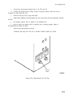
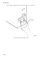
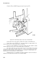
Install a 3000 psi (20,685 kPa) gage and input line hose (fig. 20-27).
Figure 20-27. Install Pressure Gage in Input Lines to Fail-Safe Brake.
(5)
start engine and set cab controls to operate winch. (Refer to TM 9-2320-273-10.)
(6)
push down on winch CONTROL NO. 1 and record indication from gage installed in the
input line hose (fig. 20-27). Should indicate 2500 psi (23,238 kPa).
(7)
pull up on winch CONTROL NO.
2
and record indication from gage installed in auxiliary
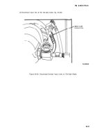
hydraulic system OUT port (fig. 20-25). Should indicate 2000 psi (13,790 kPa).
(8)
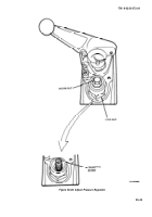
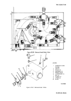
If results of either test is not correct, remove the acorn nut (fig. 20-28) from the pressure
relief valve that needs adjusting (CONTROL VALVE NO. 1 or NO. 2). Loosen adjusting screw locknut
and adjust the pressure as follows. Turn the adjusting screw in (clockwise) to increase pressure. Turn
adjusting screw out (counterclockwise) to decrease pressure.
(9)
Repeat step (6) or (7), as applicable, and adjust as described in step (8) until results are
satisfactory; then reinstall locknut and acorn nut on pressure regulator.
20-42
Back to Top

