TM-9-2320-273-34 - Page 727 of 801
TM 9-2320-273-34
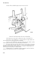
(70) Shutdown the engine and winch controls in cab. (Refer to TM 9-2320-273-10).
Before removing gage installed in the
auxiliary out port be sure pressure has
been relieved (gage at zero) by moving
number 2 control lever to the fast position.
(11)
Remove both test gages.
(12)
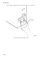
Install plug in OUT port (fig. 20-24).
(13)
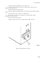
Connect input line to fail safe brake (fig. 20-26).
j.
Install front cover on control panel and secure with six screws.
k.
Install spare tire hoist (M916 only).
1.
Install spare tire (M916 only).
20-14. Orifice Removal.
a.
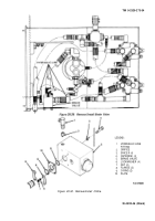
Unscrew and remove six capscrews and washers; remove control panel cover (fig. 20-1).
b.
Disconnect hydraulic lines (fig. 20-29). Remove brake valve (5) by unscrewing four nuts (7),
Iockwashers (6), capscrews (4), spacer (3), two O-rings (9), flange (8) and plate ( 10). Place brake valve (5)
in vise.
c.
Remove fitting (1, fig. 20-30) from brake valve.
d.
Using a hex key wrench, remove orifice (2) from valve inlet.
e.
Cleaning and Inspection.
(1)
Using a pin or a piece of wire and cleaning solvent (item 12, Appendix B), clean out
small hole in orifice.
(2)
Inspect for damage. If unrepairable, replace orifice.
b.
Installation.
(1)
Install orifice (2) in valve body through inlet and tighten securely with a hex key wrench.
(2)
Coat threads of fitting (1) with liquid teflon (item 14, Appendix B) and install in valve.
(3)
Remove brake valve (5) from vise and place in mounting location on winch assembly.
Secure with four capscrews (4), spacer (3), Iockwashers (6), nuts (7), two O-rings (9), flange (8) and
plate ( 10).
(4)
Connect hydraulic lines and check for leaks.
20-44
CAUTIO N
Back to Top

