TM-9-2320-273-34 - Page 720 of 801
TM 9-2320-273-34
(6)
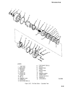
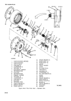
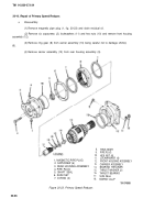
Remove shaft seal (5) from rear housing assembly (3) and discard.
(7)
Remove bearing cups (18) only if replacement is necessary.
b. Assembly.
(1)
Clean all parts using drycleaning solvent SD 2 (item 12, Appendix B).
(2)
Inspect all parts for damage or excessive wear; replace as necessary. Check O-rings (7)
for nicks or signs of deterioration and replace as needed.
(3)
Assemble sun gear (17), two thrust washers (15) and thrust bearing (16) and install on
bearing retainer (14) and into carrier assembly (13).
(4)
Install new shaft seal (5) in rear housing assembly (3).
(5)
Install magnetic pipe plug (1) in rear housing assembly (3).
(6)
Install carrier assembly (13) with sun gear (17) in place into the rear housing assembly
(3).
(7)
Install two capscrews (2) through opposite sides of mounting flange of rear housing
assembly (3). Hold capscrews in place and install shim(s) (6), ring gear (8) with two O-rings (7) and front
housing assembly (12). Install two Iockwashers (11) and hex nuts (10) finger tight.
(8) Install remaining
four capscrews (2), Iockwashers (11) and hex nuts (10). Torque to
17 Ib-ft (23 N•m).
20-11. Winch Reassembly.
a.
Inspect bronze bushing (5, fig. 20-14). If bushing is scored or otherwise defective, replace.
On installation, use Loctite No. 601 (item 19, Appendix B) to secure bushing.
b.
Install new oil seal (4). Seal should be flush with end of drum when installation is correct.
c.
Coat seal (4), inside of bronze bushing (5), and the drum female spline teeth with an all purpose
grease (item 1, Appendix B).
d.
Mount assembled final drive housing (11) and gear support (12) on drum support (10), mating
the male gear on the final drive with the female spline gear in the drum. It may be necessary to tap the
final drive with a rawhide mallet to seat it fully.
e.
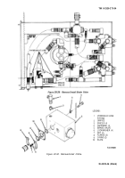
Using a sling and hoist, support winch drum and set assembly on its side rails, as shown in
figure 20-14, sheet 2.
f.
Install six capscrews, nuts, and washers (13) that fasten final gear support (12) to both side
rails (14). Tighten to 275 Ib-ft (373 N•m) torque.
g.
Install input shaft in center of drum (small diameter end of shaft towards final drive gear).
h.
Stand the winch of final gear drive end, as shown in figure 20-14, sheet 1.
i.
Inspect bronze bushing (15). If bushing is scored or otherwise defective, replace. On installa-
tion, use Loctite (item 19, Appendix B) to secure bushing.
j.
Install new oil seal (16). Seal should be flush with end of drum when installation is correct.
20-37
Back to Top

