TM-9-2320-273-34 - Page 717 of 801
TM 9-2320-273-34
(4)
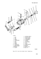
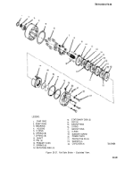
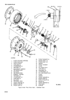
Assemble secondary carrier (7) as follows:
(a)
Apply a light coat of Loctite to outer surface of bushing (2); then press bushing
into bore of output shaft (3).
(b)
Insert output shaft (3) into splines of secondary carrier (7); then install retaining
ring (8) on output shaft (3).
NOTE
In step
(d)
use Lubriplate (item 16,
Appendix B) or a grease with a low melt-
ing point to retain needle rollers (35)
when they are assembled into pinion gears.
(c)
Assemble 16 needle rollers (35) into one end of each pinion gear (34).
(d)
Install spacer (36); then assemble 16 needle rollers (35) into the other end of
pinion gear (34).
(e)
Install each assembled pinion gear (34) into secondary carrier (7) and install thrust
washer (37) and (33) between each gear (34) and inside walls of carrier. Make sure that tabs on thrust
washers are alined with recess in the carrier.
(f)
Install three pinion shafts (22) into carrier and through each pinion gear (34). Aline
pinion shafts (22) so that retainers (6) can be installed in shaft slot.
(g)
Apply Loctite (item 19, Appendix B) to threads of capscrews (4); then install with
Iockwashers (5) to secure each retainer (6) to secondary carrier (7). Tighten to 27-32 Ib-ft (37 N•m)
torque.
(h) Check end play of each gear (34). Should be 0.004 to 0.020 in. If end play is more
than 0.020 in., replace thrust washers (33 and 37).
(i)
Check each pinion gear (34) to determine that it rotates freely, without binding or
restriction.
(5)
Assemble primary carrier (11 ) as follows:
(a)
Install retainer ring (10) on shoulder of sun gear (9); then slide the gear into splines
of primary carrier (11).
(b) from inside primary carrier (11), install retaining ring (16) in groove of sun gear (9).
NOTE
In step
(c),
use Lubriplate (item 16, Appendix
B) or a grease with a low melting point to re-
tain needle rollers (18) when they are assembled
into bore of pinion gear (19).
(c)
Assemble needle rollers (18) into each pinion gear (19).
(d)
Install each pinion gear (19) into primary carrier (11), and install thrust washers
(20) and (17) between the gear and the walls of the carrier. Make sure that tabs on thrust washers (20)
and (17) are alined with recess in the carrier.
20-34
Back to Top

